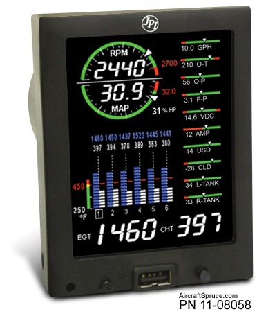
Insight G4 Graphic Twin Engine Monitor
от 443546 369622 руб.
до 1543932 1286610 руб.
Наличие: Проверяйте наличие по каждому товару
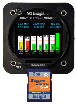
Overview
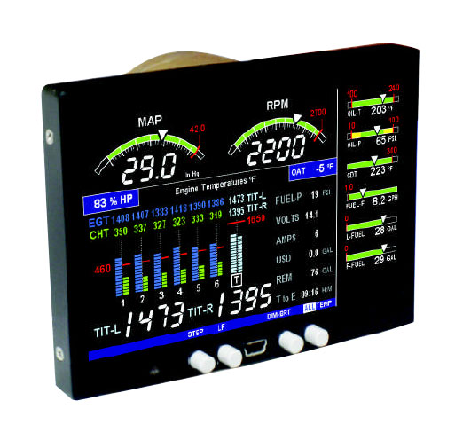
Insight Graphic Twin Engine Monitor G4
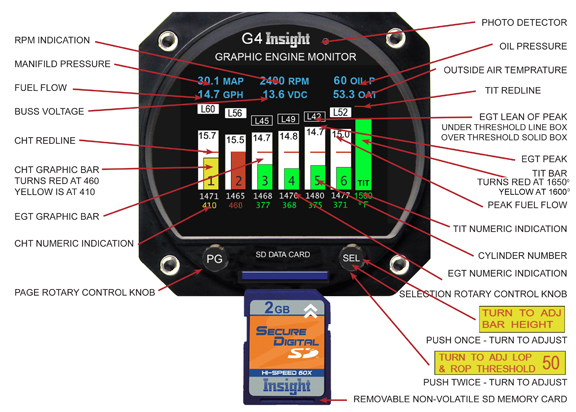
Special Lean Of Peak Functionality / Unparalleled ease of operation / Nozzle balance analysis every time. Insight's 610C Graphic Engine Monitor (G4) colour-coded bargraph and digital values may be Primary for CHT , EGT and TIT. All other data shown in cyan at the top of display are to be supplementary. Traditional multi-cylinder exhaust gas and cylinder head temperature systems that force the pilot to switch or scan an indicator from cylinder to cylinder in search of critical engine data, are long obsolete. Using the latest computer technology, the G4 presents a clear, concise, graphic picture of all engine temperatures simultaneously for interpretation at a glance. Never before has so much engine diagnostic information been available to the pilot and never before, has the pilot been able to control mixture with such ease and precision for peak fuel efficiency. Insight's latest G4 automatically records flight temperature and will also interface with other data sources and report information to other instruments like MFD?s. The data-log files stored on the SD card can be easily retrieved by the pilot, in-flight or post-flight, for instant viewing or permanent record-keeping. The G4 is a sophisticated tool for engine management. Its microprocessor performs many tasks that used to be handled by the pilot. One of the basic functions performed by the G4 is monitoring exhaust gas temperatures for all cylinders with one degree resolution. What is important is the exhaust gas temperature of a particular cylinder in relation to its peak. But peak EGT is not a constant; it changes with atmospheric conditions, altitude, power setting and engine condition and for this reason absolute exhaust gas temperatures in degrees Fahrenheit are quite meaningless. The real objective of mixture management is finding a mixture setting which represents the correct position on the EGT/Fuel Flow Curve. As we will see later, this abstract task is easily accomplished by the G3's microprocessor which samples EGT's for all cylinders many times a second and subjects this data to a complex mathematical analysis can identify peak. This capability allows the pilot to operate his or her aircraft engine at the most economical mixture settings. It is generally known that EGT can be a valuable source of information for engine diagnosis and troubleshooting, but there is a great deal of confusion when it comes to interpreting this data. One of the basic principles of EGT engine analysis is that engine temperatures (EGT and CHT) achieve equilibrium in an engine operating at a constant power and mixture setting. What is often overlooked is that this equilibrium cannot be defined as a single point but rather a range of temperatures. The Graphic Engine Monitor is ready to operate the moment electrical power is applied. Within seconds after starting the engine, the white EGT bar graph columns will begin to appear on the G4 display. Each column corresponds to the Exhaust Gas Temperature (EGT) of a cylinder. The lowest exhaust gas temperature that can be displayed by the G4 is 800° F. In some engines, the throttle will have to be opened to the fast idle range to get an EGT indication for all cylinders. As the cylinder heads begin to warm up, the display will indicate Cylinder Head Temperature (CHT) for all cylinders as a smaller green bar in each EGT column. A horizontal red line across each column represents the maximum allowable CHT. Digital numbers below each bar graph column indicates the exact EGT and CHT for each cylinder. G4 Buss Voltage The G4 Buss Voltage attempts to display the buss voltage in green when it?s normal and red when it?s outside of normal. In an aircraft with a 12V electrical system the Buss Voltage will be annunciated in green so long as the voltage is 12.0V to 14.9V (inclusive). In an aircraft with a 24V electrical system the Buss Voltage will be annunciated in green so long as the voltage is 24.2V to 28.7V (inclusive). Below this range the alternator isn?t charging the battery and above that it?s overcharging, and the Buss Voltage will be annunciated in red. The instrument must be connected to the main voltage buss (not in series with something else, on a lighting buss, etc) and must have a good low-resistance ground connection, otherwise the voltage measurement itself will be in error causing the Buss Voltage to indicate in red erroneously. Controlling the G4 instrument The instrument has two control knobs that operate combination rotary and push button switches. The top knob in general controls screen selection while the bottom knob controls items within the given screen. Each screen assigns its own functional needs to the controls that may change depending on context. A screen may also label the controls with guidance information like ?Push to exit?. The Bar-Graph Display Screen The Exhaust Gas Temperature is displayed in white bar graph form and is interpreted much like a conventional mercury thermometer. The higher the bar, the higher the temperature. The cylinder head temperature is displayed in green single bar format. During normal operation it shows as a green illuminated bar in the lower half of the bar column. Since EGT is normally higher than CHT, the green bar which represents CHT is on top of the white illuminated EGT bar and stands out clearly. However, when the engine is shutdown, the EGT quickly drops to zero and the cylinders remain warm for sometime. The G3 provides a reliable indication of cylinder head temperature even with the engine shut down. Should an EGT probe fail, the entire EGT column for that cylinder will go blank, and the numeric indication will show --- that is dashes, but the CHT bar will still remain green. The failure of one probe will not affect the display of any other probe. |