246-100 Cessna Vortelator Kit
Артикул: 08-00731
195030 162525 руб.
Наличие: – Есть в наличии у нашего поставщика. Доставка на наш склад в течение 5...6 недель после оплаты Вами заказа.
Overview
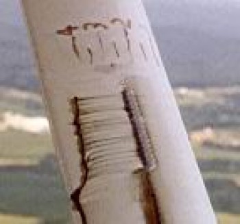
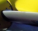
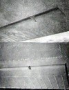
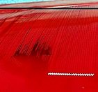
HOW VORTELATORS CONTROL THE BOUNDARY LAYER TO REDUCE AIR DRAG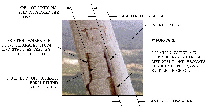 The 246-100 Cessna vortelator kit can increase Cessna speeds by up to 6 MPH. This is accomplished by placing vortelators at certain critical locations including the propeller which cause the boundary layer to stay attached to flying surfaces for a greater distance, and to keep the boundary layer thinner. The net result of these two actions is that it reduces both the profile drag and skin friction drag components of parasite drag. Another way to think of it is that the wake behind the aircraft will be smaller thus requiring less horsepower to propel the aircraft through the air. Behind the vortelator mini vortices are created as can be seen by the lines of oil that form behind the vortelator. These mini vortices sweep the oil to a point in between the mini vortices, and that?s how the oil lines are formed. Whenever one sees these characteristic oil lines forming behind the vortelator one knows the vortelator is working. The vortelator allows the air flow to stay attached to the lift strut for approximately 80% of the lift strut?s chord. In the area where there is no vortelator the air flow separates from the lift strut at approximately 40% of the lift strut?s chord, as can be seen from the pile up of oil at the 40% chord position. At the 40% chord position the lift strut is 2.01? thick, and at the 80% chord position the lift strut is 1.18? thick. That means the wake coming off the lift strut is only 59% as thick with the vortelator attached as without the vortelator attached. That also means with a narrower wake less horsepower is required to propel the lift strut through the air. Another benefit of this kit is that it is so simple to install that any aircraft owner can install the kit without any difficulty thus saving much of the installation cost. However, be advised the FAA regulations require that a licensed mechanic must work on the aircraft. Because of the simplicity of this kit installation, an arrangement can be made to do the work under the supervision of a licensed mechanic. The basic procedure for installing the kit is to prepare the surface to which the vortelator is going to be applied by thoroughly cleaning the surface. Then simply peel the liner backing off the adhesive back vortelator and apply it to the cleaned surface. We believe this kit can have a pay back in gas savings that will help offset the cost of the kit. This vortelator kit is FAA STCd and manufactured under a FAA PMA approval. The kit comes with 200 feet ofvortelator, more than enough for one airplane, and clear simple instructions on how to install the kit. The kit can easily be installed in one day and will add about 5 ounces of weight to the aircraft and not change the handling qualities of the aircraft. To be more specific the cruising speed increases one can expect from this vortelator kit is about 4 MPH for the 140, 150, 152, 170 aircraft. About 4. 75 MPH for the 172, 175, and about 5.50 for the 180, 182,185,205, and 206 aircraft. The top speed increases will be slightly higher than those listed. |


